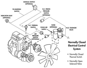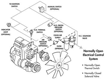

Whether a vehicle’s fan drive electrical control is normally open or normally closed can be a confusing issue. It is also an important one, since the type of electrical control system indicates the field maintenance procedures necessary in retrofitting or replacing cooling system components.
Horton fan drives are air engaged (90 – 120 psi) and spring disengaged. They operate by an electrical control system and optional controls.
The basic electrical control system consists of a thermal switch and a 3-way solenoid valve with or without an air filter.
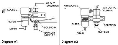
The simplest and surest method to determine whether a vehicle equipped with a Horton fan drive has a normally open or normally closed electrical control system is to inspect the solenoid valve. With a normally open electrical system you will have a normally closed solenoid valve. The normally closed solenoid valves are pictured in Diagrams A1 and A2.
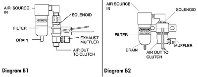
With a normally closed electrical system, you will have a normally open solenoid valve. The normally open solenoid valves are pictured in Diagrams B1 and B2.

Diagram A1:
1. Air inlet is on the top marked "IN-NO, EX-NC".
2. Air out to the fan drive is on the end marked "OUT". 3. Exhaust is on the side.
Diagram A2:
1. Air inlet is on the end or top. 2. Air out to the fan drive is on the side marked "2" or "OUT". 3. Exhaust is on the side marked "1" or "IN/EX".

Diagram A1:
1. Air inlet is on the side.
2. Air out to the fan drive is on the end marked "OUT". 3. Exhaust is on the end marked "IN-NO, EX-NC".
Diagram A2:
1. Air inlet is on the side marked "1" or "IN/EX".
2. Air out to the fan drive is on the side marked "2" or "OUT". 3. Exhaust is on the end.
Thermal Switches
The thermal switch is an integrated engine temperature control and/or over-heat protective device. Its switching circuit features mechanical load switching. It is designed for frequent or high current switching. Controls include the fan drive, radiator shutters and engine shutdown (overtemp).
Specifications:
Single pole, single throw. Instant switching action (less than .001 seconds.) No chatter.
- Ambient Temperature Range: -65 to +300 °F
- Material: Case and Terminals are brass. The header is molded plastic and is high temperature resistant.
- Current rating: 3.0 amps resistive, 3.0 amps inductive.
- Electrical source: +12VDC to +24VDC
- Life: 500,000 cycles at rated current.
- Set Point: 175-230 °F in 5° intervals.
- Set Point Accuracy: ± 2.5 °F
- Switch Mode: Normally open or normally closed.
- Differential: (reset point) Switch shall return to normal position 7 ± 2 °F below its point of operation.
Solenoid Valves
The solenoid valve controls the airflow, from the vehicle’s system, to the clutch for complete and accurate fan drive engagement.
The Horton air valves are a 3-way solenoid with a 3/64” orifice on the inlet and outlet for smooth engagements and disengagements. The valve is available in both 12 and 24 VDC.
If the air inlet enters the side of the solenoid and exhaust air releases out the end, the electrical control system is normally open. If the air inlet enters the solenoid from the top and exhaust air releases out the side, the electrical control system is normally closed.
NOTE
If using a solenoid valve not supplied by Horton, use a 3-way normally open valve with a 3/64” inlet and outlet orifice.
If you fan drive is ECM controlled, it will use a normally open solenoid.
Air Conditioning Pressure Switch
The A/C pressure switch actuates the fan drive when the refrigerant pressure reaches the maximum switch setting. It is normally open and is used with normally open electrical systems.